
OPUS CAD - 2D and 3D geometry
This module contains all possibilities of NC-specific contour and drill point manipulation. It
the construction of complicated geometries as well as the generation of hole patterns.
(point patterns). The generated geometry can be used as tool, blank, clamping sketch, finished part for
cutting layout or as an NC path.
Geometriy creation
- Easy geometry creation (2D and 3D)
- Direct generation of NC blocks (commented DIN 66025)
- Transformation, copy and delete functions
- Correction of the calculated path possible at any time
- MDI capable (exchange between windows via clipboard)
- NC-specific contour manipulations: Chamfers, undercuts, fillets, cutter radius compensation and cutter path correction
- Subsequent insertion and editing of radii and chamfers
- Reading and saving of individual contours and complete images to the part program, to files or databases
- Mirroring, rotating and moving of the drawing / machining (2D nd 3D)
- Transfer of contours from other NC projects
- Dimensioning functions
CAD data transfer from the design
2D CAD Import
- DXF / DWG
- IGES 2D
- A11
- PIC (CADdy)
- MI (ME10 - HP)
- other formats on request
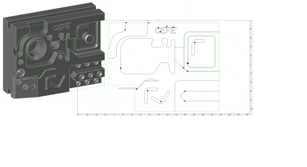
The workpieces designed in the CAD system are taken over by the OPUS system. Thus the renewed definition of contours for the machining operations is not necessary. Elements contained in the drawing can be filtered according to drawing layers, colors and line types. Thus, the processing of the data received from the CAD system can be minimized. The received data can be manipulated in OPUS, according to the required machining, at any time. Important workpiece zero points for the manufacturing can also be set subsequently.
3D CAD Import
Supported formats:
- ACIS (.sat, .sab)
- Solidedge (.par, .asm)
- NX (.prt)
- JT (.jt)
- Parasolid (.x_t, .x_b, ...)
- CATIA V4 (.model)
- CATIA V5 (.CATpart)
- Pro/E oder Creo (.prt, .asm)
- Solidworks (.sldprt, .sldasm)
- Inventor (.ipt. iam)
- IGES (.igs, .iges)
- STEP (.stp, .step)
- STL (.stl)
- VDA-FS (.vda)
CAD-Converting (Export from OPUS CAD)
3D CAD Export
From Interop supported formats for writing:
- ACIS (.sat, .sab)
- Parasolid (.x_t)
- CATIA V4 (.model), V5 (.CATpart)
- IGES (.igs, .iges)
- STEP (.stp, .step) AP203, AP214, AP242 (nur Geometrie)
- STL (.stl)
- VDA-FS (.vda)
- 3D PDF (.pdf)